It is not a 007 film or novel, it is an antenna from Russia. Antenna design, homebrew and experiments are a true science and RF engineering for a real homebrewer. It will expose more hidden things, it will reveal more things in radio frequency, propagation, gain, F/B ratio, SWR, attenuation etc. Truly it is an art.
In the search of the unusual antennae in HAM radio, in last march 2013, I published two unusual designs; Hentenna - an ADR antenna and Tilted-V VHF 2m antenna in hamradio.in. Now I am going to publish a Russian VHF 2m antenna design that I homebrewed and tested thoroughly. It is a very simple, high gain and directional antenna for 145 MHz VHF band. Nikolay Kudryavchenko - UR0GT was published this design. Its gain is 4.9 dB and it will give 15 dB F/B ratio.
This unusual antenna is having only two things; One is a rectangle loop and the other is a reflector. It will produce a CARDIOID pattern (heart shaped). Two ground plane array with a proper phasing will produce the same pattern but it needs a phase difference of feedline (refer VHF Amateur Radio - By William Orr, W6SAI - Page 7.15 and 7.16). But in this Russian Antenna there is no need of such a feed line!!. It is a direct feed Antenna and no matching or no tuning (See the feed point photos). So this antenna is very simple and economical for a homebrewer.
At the first ‘on air test’ with VU2UJE (MK80hs), I was at ground level in low power inside the QTH at MK80ht. It was 5-9 plus. Then the test was through VU2KOD repeater at 7000 feet MSL, 110 km distance from my QTH. My elevation was at 300 ft. MSL with portable inside the QTH and the signal report was 5-6.
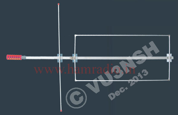
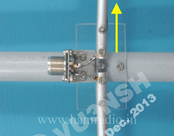
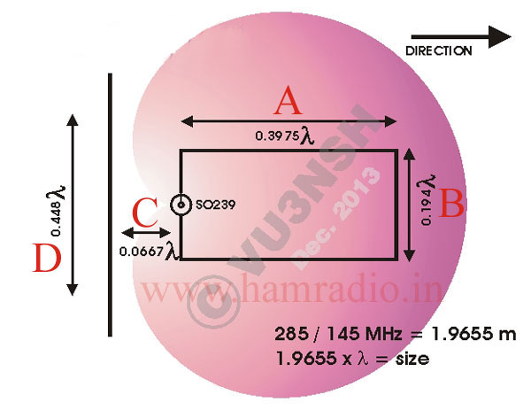
Combination of the rectangle is 0.194 λ, 0.3975 λ and the spacing of reflector is 0.0667 λ. The length of the reflector is 0.448 λ (See figure 3). I made this antenna with 3/8" aluminum tube, and fix it on a 1" PVC tube with a handle for portable test (You can see it in the photograph). As per Nik UR0GT article you can see www.antentop.org/016/files/card_016.pdf.
This antenna can be converted for 3m FM broadcast band and also one can try for 70 cm amateur band. Refer the measurement tables for these bands.
For 3 m FM Radio Band - (Not for Transmitting)
λ = 285 / 98 MHz = 2.9081 m
Side A = 2.9081 x 0.3975 = 1.15596 x 100 = 115.59 cm
Side B = 2.9081 x 0.194 = 0.5641714 x 100 = 56.417 cm
C (Spacing to Refl.) = 2.9081 x 0.0667 = 0.193970 x 100 = 19.397 cm
D (Refl. length) = 2.9081 x 0.448 = 1.30282 x 100 = 130.282 cm
For 70 cm Amateur Radio Band
λ = 285 / 435 MHz = 0.6551724 m (65.517cm)
Side A = 0.6551724 x 0.3975 x 100 = 26.043 cm
Side B = 0.6551724 x 0.194 x 100 = 12.710 cm
C (Spacing to Refl.) = 0.6551724 x 0.0667 x 100 = 4.369 cm
D (Refl. length) = 0.6551724 x 0.448 x 100 = 29.3517 cm
This simple Antenna is equivalent to a 2 element yaagi. Such an antenna will produce an ERP at 5 Watts input is equal to 15 Watts ERP and in 50 Watts input it will produce 150 Watts ERP because 4.9 dB gain means three times power gain. So have a nice homebrew of the same antenna ‘From Russia with L♥ve’.